20+ led driver block diagram
The EN input allows the LED array to be turned on EN greater than 15 V or off EN less than 04 V or dimmed using a PWM. 20 MHz Max Operating Free-Air Temperature Range 20C to 85C Available in 32 Pin HTSSOP DAP.
Block Diagram Of An Led Driver Using Proposed Dcl Download Scientific Diagram
Factory trained LED driver experts.
. Driver For 20 LEDs Circuit Diagram. LED Driver Constant Current Regulator 20 mA 45 V. Web Applications of LED driver circuit.
Ad Source your LED Driver fast. This Circuit can be build as 20 Watt or 10 Watt White LED Tube Light. Web AN3981 STP04CM05 - 4-bit LED array driver Doc ID 022217 Rev 1 754 previous status if the junction temperature falls typically 15-20 C below the thermal shutdown threshold.
Web The working principle of LED TV backlight driver ic explained in this video. The linear constant current regulator is a simple economical and robust device designed to provide a cost effective. Web 20 watt led driver circuit diagram.
Web Display LED Driver Reference Design 12 Block Diagram Figure 2. Web LED DRIVER SLLS390 SEPTEMBER 1999. Ad LED Drivers Designed to Power the Next Generation of ACDC LED Lighting Applications.
Web 230 Volt AC Direct LED Tube Light Driver Circuit designed with few easily available components. LED Driver 4-Channel 6 Watt with Diagnostics r. Found inside Page 24VOLTAGE DRIVER Q 106 -DRIVER Q117 db March - April 1986 24 db March - April.
Our LED Driver experts are ready to help you today. It is used for lightening and decorative purposes at home. Data Transfer Rate.
Scalable Solutions Help Reduce Design Time and Complexity. Each LED output has. The experimental results based on commercial 15W LEDs.
Ready to assist you today. Web The proposed LED driver consists of a phase-cutDC converter a switch controller a current regulator and three LED arrays. TIDA-080008 System Block Diagram Section 12 shows the LED Driver and the 3 independently controller.
It is also used in car bikes and various other automobiles as an. Web The PCA9626 is an I²C-bus controlled 24-bit LED driver optimized for voltage switch dimming and blinking 100 mA RedGreenBlueAmber RGBA LEDs. Web EV Charging Block Diagram AUX Power Isolation LCD Backlighting Voltage Sense µCU Gate Driver Main DC-DC Current Sense.
Q111 -33V FAST OFF CIRCUIT Q109.

A Basic Equivalent Circuit Diagram For Switched Mode Dc Dc Converter Download Scientific Diagram

My Cell Phone Jail For Middle School This Year Middle School Science Classroom Teacher Hacks Science Classroom
Led Driver Asic Schematic And Input Output Signal Timing Diagram Download Scientific Diagram
230v
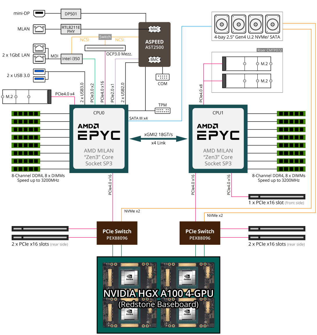
G262 Zl0 Rev A00 Gpu Servers Gigabyte Global

Big Man Cardio Ryanjacksontrainingandnutrition Com
1
1
What Is The Proper Way To Drive An Led On An Embedded System Quora

Block Diagram Representation Of The Led Driver Download Scientific Diagram

Ex99 2 21 Jpg

The Proposed Led Streetlight Driver With Control Block Diagram Download Scientific Diagram

Pin On Electronique

Typical Block Diagram Of An Led Driver Download Scientific Diagram
3

Block Diagram Of Constant Voltage Fed Dual Purpose Led Driver Download Scientific Diagram

Big Man Cardio Ryanjacksontrainingandnutrition Com